


Introduction to CAD
In the present competitive world manufacturing industries are going through lot of challenges.Earlier CAD system used to focus on improving the productivity of draftsman. However, with the change in time, the industries are looking for more efficient solution at the earliest before actual production. This has been achieved through integration of CAD with DFMA. The integration requires (CAD with DFMA) understanding of its data structure and its related mathematical representation. On this line, there are many geometric models such as wireframe,surface and solid model are available in the literature. Modeling techniques are decided based on the expected utilization of the resulting database later in the design and manufacturing process.Geometric Representation in CAD
Commonly used geometrical models are wireframe model, surface models and solid model.1. Wireframe model
It is the simplest geometrical model an object and used to represent mathematically in the computer. It is also called edge representation. Wireframe model consists of points, lines, arcs and circles, conics and curves. It doesn’t require much computer time and memory and hence is considered to be the simplest. The major disadvantage is the ambiguous representation of real object and purely depends on human interpretation. In fact, the interpretation of the correct object becomes difficult in the case of complex model.This limits the application of wireframe models from engineering viewpoint. A typical wireframe model of a cube has been shown in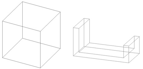
wire frame model
2. Surface model
Shape design and representation of complex object such as bodies of car, ship, airplane etc can’tbe represented by wireframe model. In such cases surface models are to be used for precise and
accurately representation. In comparison to wireframe model, surface models of an object
provide more complete and less ambiguous representation. In the surface model, the geometry of
the object is defined without storing any information about topology. For example if two
surfaces are joined, they share one wireframe entities edge. But neither the surface nor the
entities store such information. Surface representation can be done in both parametric and nonparametric form. In order to use surface for both computation and programming purpose, it is
required to develop proper equation and algorithms Figure M8.1.2 shows an example of a
surface model. Types of surface available in CAD/CAM systems are, Plane surface, Ruled
surface, Surface of revolution, Tabulated cylinder, Bezier surface, B-spline surface, Coons patch,
Fillet surface, and Offset surface.
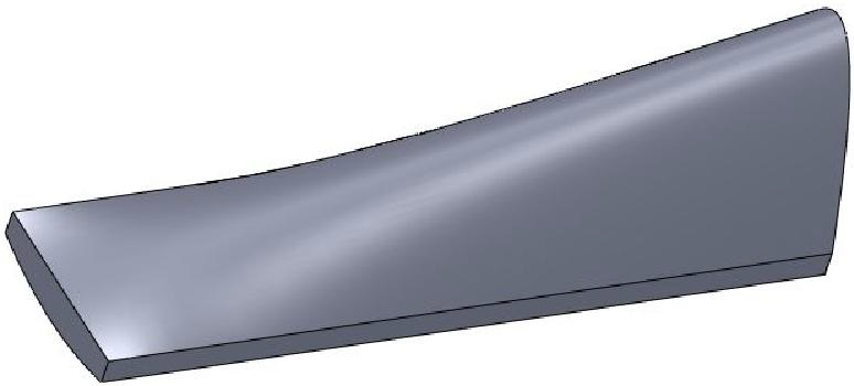
Figure M8.1.2: Surface model
3. Solid model
A solid model of an object provides more complete representation than its surface model. Thedatabase of the solid model stores geometric data and topological information of the corresponding object. Geometry is the actual dimension that defines entities of the object whereas topology on the other hand is the connectivity and associativity of the object.The geometry and topology is explained through the following example shown in Figure M8.1.3.

Geometry:
Length of the line L1, L2 & L3, and the angle between the lines and radius R and center P1 of the half circle.Topology of the object:
L1 shares a vertex(point) L2 and C1, L2 shares a vertex with L1 and L3, L3 shares a vertex with L2 and C1, L1 and L3 don’t overlap, P1 lies outside the object,where as the other case P1 lies inside the object.For creating solid models of objects various representation schemes have been designed anddeveloped. Such scheme are, Half space model, Boundary representation, Constructive solid
geometry, Sweeping, Analytic Solid modeling, Cell decomposition, Spatial enumeration, Octree
Encoding, Primitive Instancing. Boundary representation, Constructive solid geometry,
Sweeping are the most commonly used schemes.Representation of solids are built and interacted
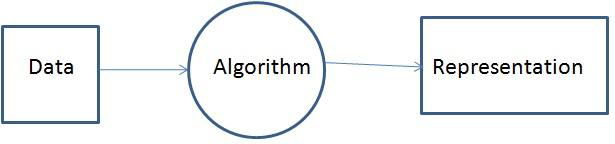
via algorithm. Such algorithms are classified into the following categories:
Data to Representation:
These algorithms can produce representation by taking data as input.These algorithms are capable of building, maintaining and managing representation.
Representation schemes fall in this category.
Theory and Practice)
Representation to Data:
These types of algorithm used to compute property values by taking input as representation. For example, computation of volume, mass and inertial property etc.
and Practice)
Representation to Representation:
These types of algorithm take a representation as input anda representation as output. Example:Algorithm converting a Constructive solid geometry(CSG)
to B-Rep.

CAD/CAM Theory and Practice)
Boundary Representation:
Boundary representation is one of the most popular representation schemes widely used to createsolid model. A boundary model (shown in Figure M8.1.7) isbased on the topological notion that
a physical object is bounded by a set of faces. These faces are regions or subsets of closed and
orientable surfaces. An orientable surface is one in which it is possible to distinguish two sides
by using the direction of surface normal to point to the inside or outside of the solid model under
construction. Each face is bounded by edges and each edge is bounded by vertices. The data base
of boundary model contains both geometry and topology

The general data structurefor boundary modeling is shown in Figure M8.1.8.
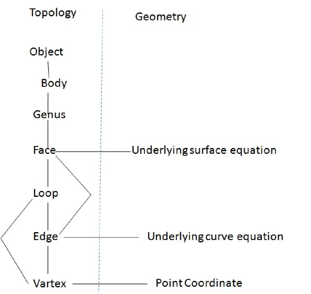
Figure M8.1.8: General data structure for boundary modelling
Constructive solid geometry (CSG):
According to CSG model a physical object can be divided in to set of primitives (basic element or shapes) that can be combined in certain order following a set of rules (Boolean operation) to form the object as shown in Figure M8.1.9. Primitives are also valid CSG model. Each primitive is bounded by a set of surfaces usually close and orientable.Through boundary evaluation process, the primitivesurfaces are combined and the boundary of the object is formed in turn, the faces edges and vertices
are obtained.
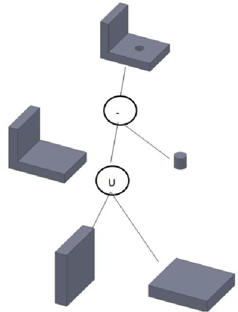
Figure M8.1.9: Constructive solid geometry
Sweep representation:
These types of representations are useful in creating solid models of two and half dimensionalobjects. The class of two and half dimensional objects includes both solids of uniform thickness
in a given direction and axisymmetric solid. The former are extruded solid and are created by
linear or translational sweep and the later are the solids of revolutions which can be created by
rotational sweep as shown in Figure M8.1.10 and Figure M8.1.11.
Figure M8.1.10: Translational sweep
Figure M8.1.11: rotational sweep
Feature based model:
Feature and feature-based terms are used in feature-based model. However, the above twoterminologies have been used in different meaning by different researchers. Definitions available
for these terminologies in the literature are provided here. Those are Features represent shapes
and technological attributes associated with manufacturing operations and tools [Shah 1990].
Features are groupings of geometric or topological entities that need to be referenced together
[Shah 1990]. Features are elements used in generating, analyzing, and evaluating design [Shah
1990]. Features are set of information related to an object’s description. This description could
be for design, for manufacturing or even for administrative
purposes. In this post, features represent the engineering meaning of the geometry of a part or assembly which is summery of the above definition. Shah and Rogers[Shah and Rogers,1988] classified
features into setsrelated to product engineering application as follows:
- Form features
- Material features
- Precisions feature
- Technological features
The feature is agsin sub classified as follows:
- Form features
- functional
- aesthetic
- assembly aids
2. Material features
- properties/specifications
- treatment, applied to materials andsurfaces
3. Precisions feature
- tolerances
- surface finish
4. Technological features(information related to part performance and operation)
- performance parameters
- Operating variables
- Design constraints.
0 comments:
Post a Comment